High-Altitude Solar-Heated Balloon Research Observatory With Wind Navigation

High Altitude Solar Balloon Project: Year 2
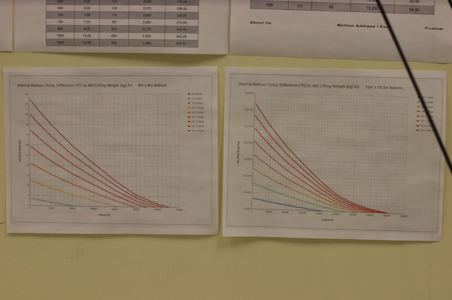
This engineering project, funded by Dartmouth College, set the goal of building a high-altitude solar-heated ultra-lightweight balloon capable of lifting a 7 kg payload up to 100,000 ft above sea level. The project spanned two years, and in that time we made 8 prototype balloons ranging from 3 to 12 meters in diameter. The first year was dedicated to researching the components and materials to be used (see HASHBROWWN: materials).
The second year focused on:
1) Assembling the components into a cohesive functioning system.
2) Scaling up prototypes from the smaller 3 m diameter to the largest 12 m diameter balloons (and solving issues associated with scaling)
3) Developing methods for launch, cut-down, and ground control
4) Designing and prototyping a re-sealing vent which could jettison hot buoyant air and drop the balloon in altitude.
5) Assembling a payload which would record video, track coordinates (GPS) and communicate directly with ground control up to 60 km away via direct antenna communication. Payload PCB was repurposed from previous use in ALTAIR (linked below)

6 um Mylar was the main material we used to construct the envelope of the balloon. (See HASHBROWWN: MATERIALS)
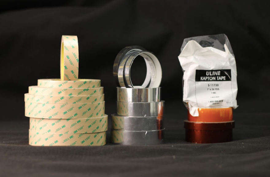
Various Tapes rated to below -60°C were used in the construction of the balloon. (See HASHBROWWN: MATERIALS)
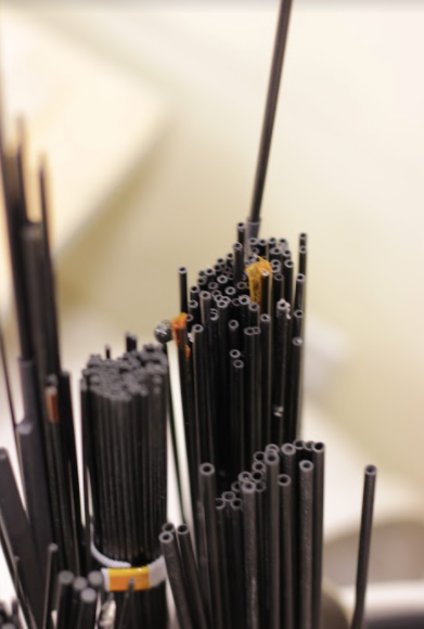
Carbon Fiber Rods were used to provide a more rigid structure upon which the payload could be attached. This had the added benefit of increasing the internal volume of the balloon by holding it out in a cylindrical shape.
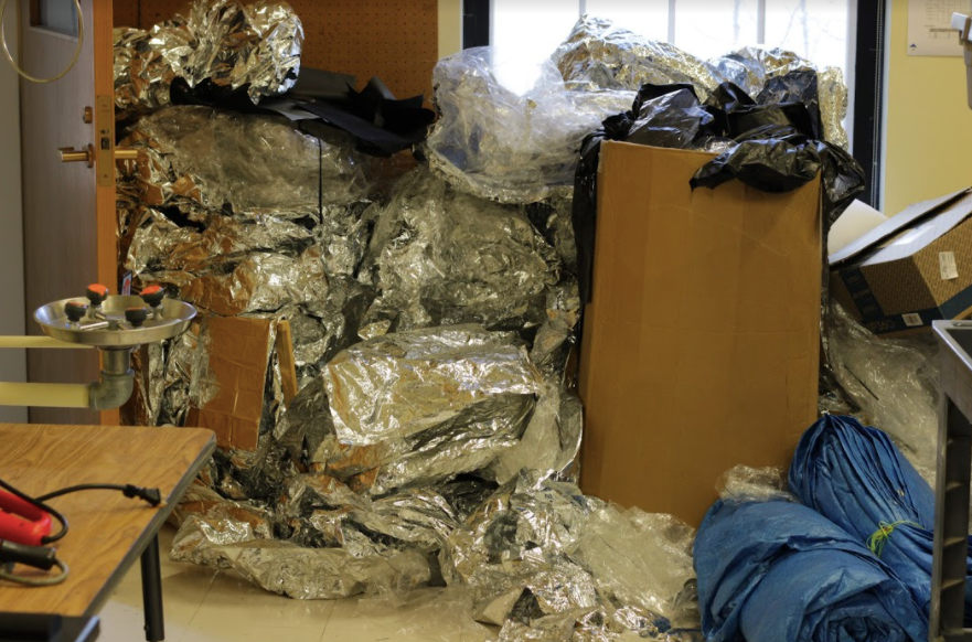
Past Prototypes were kept for reference. Occasionally before implimenting an idea in our larger 10-12 m diameter balloons, we would run a trial on the smaller 3-4 m diameter prorotypes.
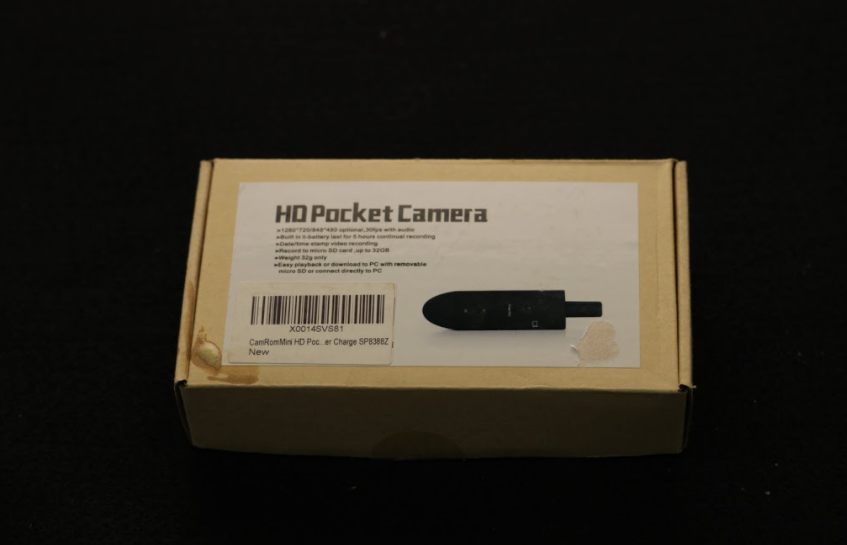
This Pocket Camera was placed on the payload and gave us a realtime view upward to the venting system. If there was a problem at altitude (e.g. line tangle or an otherwise stuck vent) we would be able to see it.
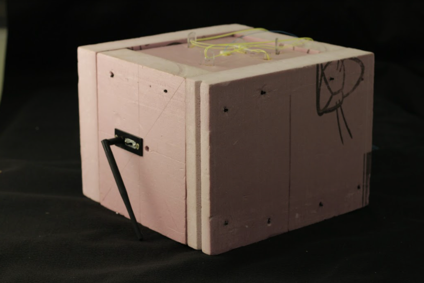
The Payload contained and antenna, a live GPS, two motors and capstans for vent actuation and payload cut-down, a PCB for telemetry, and a backup GPS spot (for offline use). The payload weighed in under 5 kg with a 7 kg constriant. The density requirement set by the FAA (for aircraft impacts) was met using insulation foam. The pannels of the payload could be disassembled easily for fast servicing. On launch days, the payload was wrapped with bright orange duck tape (for visibility)
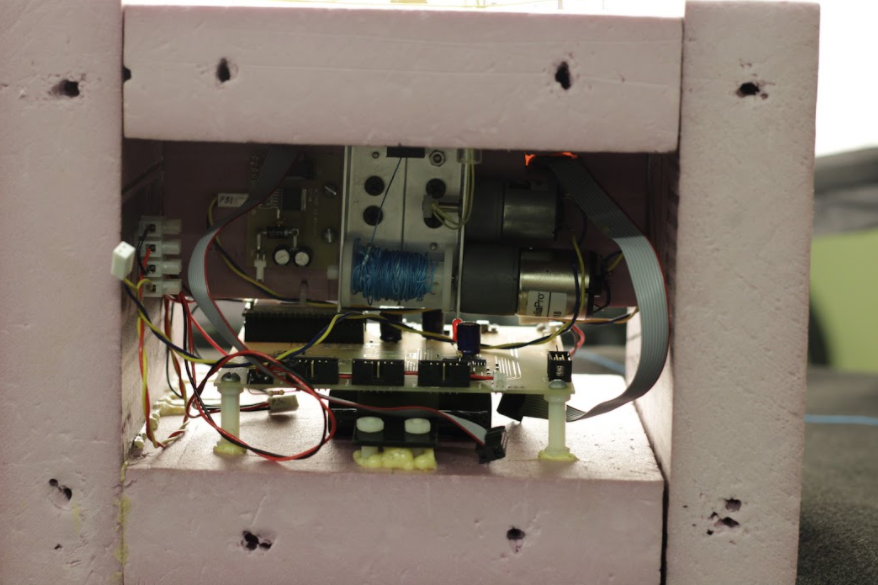
An Interior View of the Payload shows the motor and spool for vent actuation (blue line), the smaller motor for cut-down, the PCB (repurposed from ALTAIR), and the antenna connections.
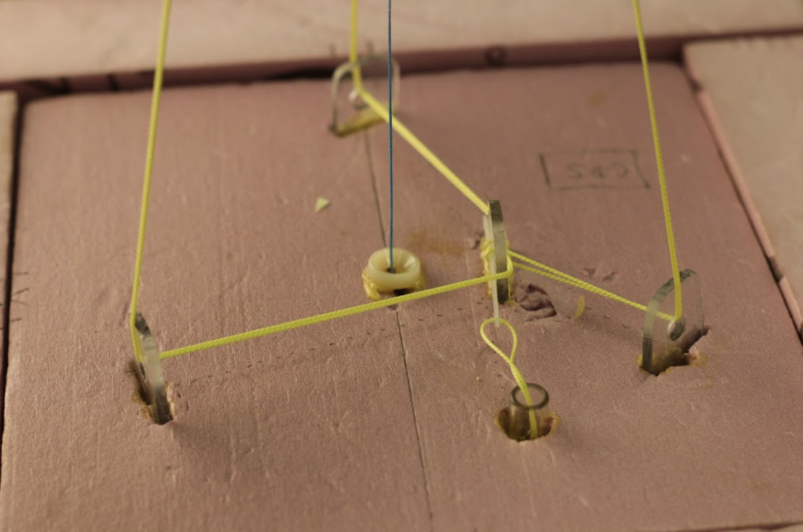
Cutdown Mechanism The FAA requires two methods for balloon cutdown. Primary cutdown was acheived by a motor pulling a small pin and releasing three cables supporting the payload below the balloon's bottom skeletal ring (yellow lines). Once actuated, the payload could fall away from the balloon and return to the ground using a parachute. The second method involved pulling the vent open using the blue line seen in this image. This will remove any buoyant warmer air from the top of the balloon and cause a severe drop in altitude.

Our Smallest Operational Balloon This cylindrical balloon, which is rolled up tightly in this photo, has a diameter of 4 m and a height of 6 m. The image at the top of this page showcases this balloon in flight.
Interior of 4 m Balloon This photo, taken from inside the 4 m balloon, shows the open hole at the bottom in our design. This hole ensured zero pressure difference between the inside and the outside of the balloon no matter the ambient pressure. Our "zero-pressure" balloon would not need to expand (or run the risk of popping) at high altitude. The relative internal pressure and resulting lifting force would be solely a function of temperature differential.
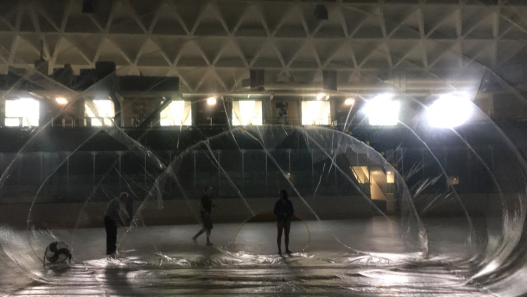
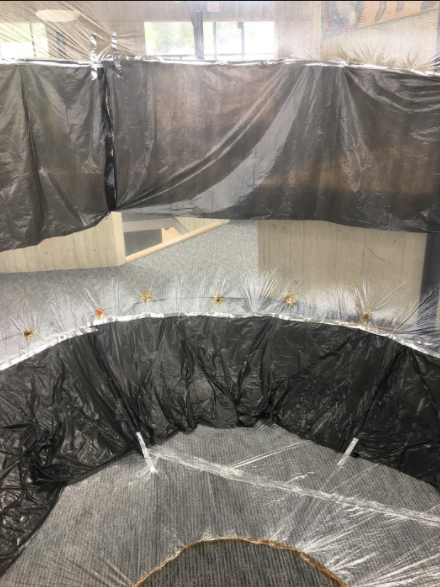
Interior of 12 m Balloon This balloon had a 12 m diameter and an 18 m height. It was so large that we had to construct it on the floor of the hockey arena. This photo is taken from within the balloon when it is half inflated and lying on its side.

Constructed in an Arena Our 10 and 12 m balloons required a large, windless construction area. The Thompson Hockey Arena during the summer seemed to be the best location.
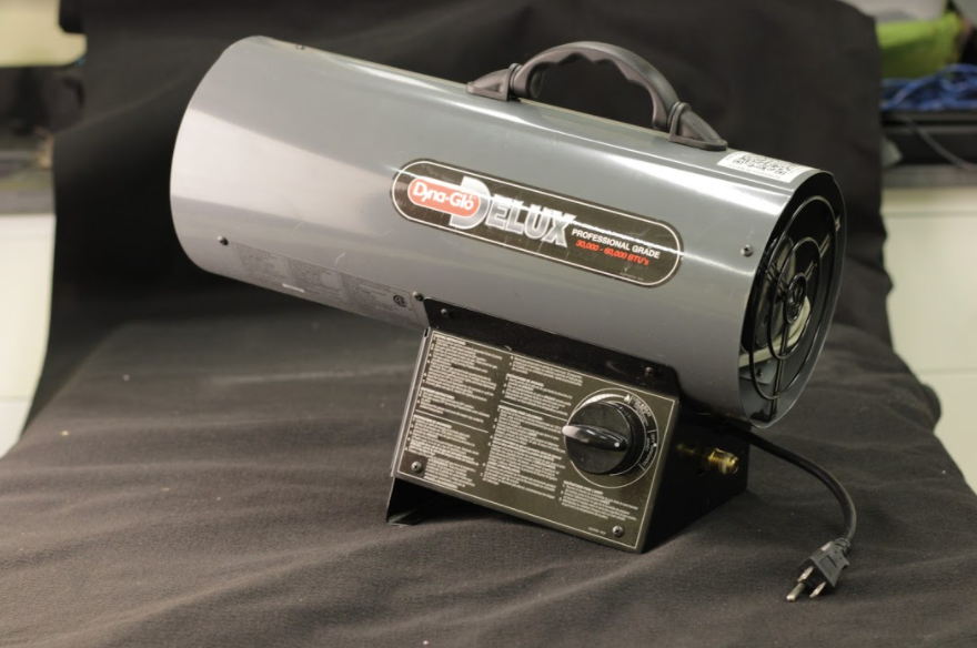
Salamander This construction propane "space heater" was used on cloudy launch days to inject hot air into the balloons as a boost before the sun took over above the cloud layer.
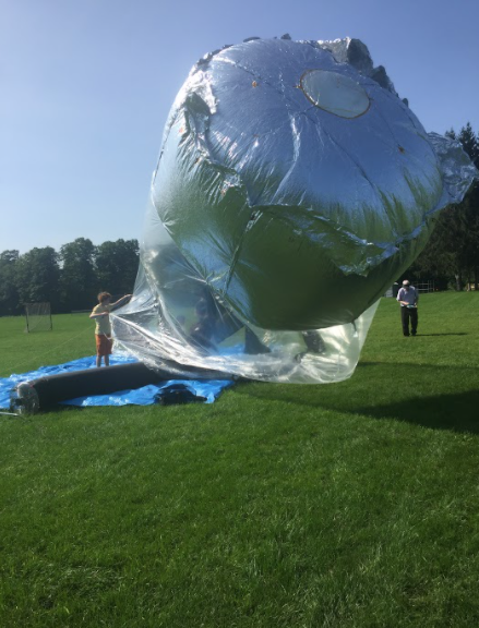
Partially inflated 4 m balloon The finalized vent design can be seen atop the silver cap of this prototype. The vent's tight seal was acheived using the upward pressure of the hot air within. We used a "wacky waver" nylon tube (black structure attached to fan) to aid in the inflation of balloons on particularly windy launch days.
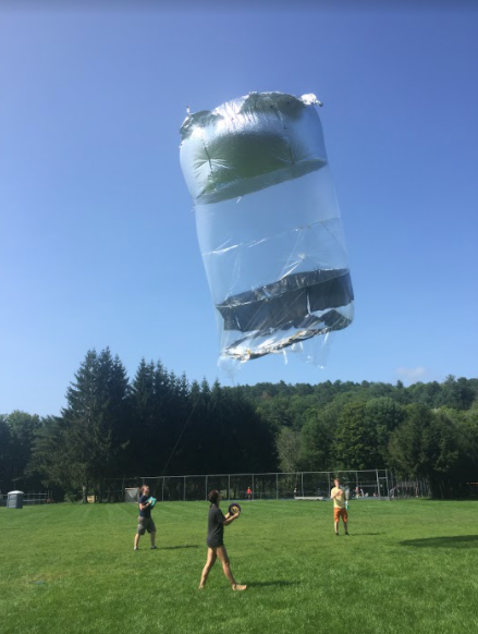
Our smallest (4 m) Balloon in Flight This was during a low altitude test of a polyethylene absorption material.

Flight Diagram This diagram describes the flight of a similar balloon built by the French in the 1970s. This balloon was launched at night and used only the earth's infrared radiation to provide heating to the air within. The balloon failed on a cloudy night when the infrared was obstructed.